FAQs
Sonifex Redbox Frequently Asked Questions (FAQ)
 This FAQ (frequently asked questions) answers some of the popular questions asked about the Redbox range. If you have any specific questions regarding the operation of Redboxes which aren't covered below, please contact your nearest distributor, or Sonifex directly.
Related Links:
The Redbox Range
Redbox Catalogues and Handbooks
RB-DEED8 & RB-VHEDD8
Dolby Embedder, Unbalanced Input Grounding
The Redbox Dolby® Encoder products use differential inputs that can be terminated with either 75Ω or 110Ω for unbalanced or balanced inputs, respectively.
For unbalanced inputs, all that should be required is to set the inputs to 75Ω. However it has been found in rare circumstances that in this case there are issues with grounding when the input is connected from other manufacturers’ products.
Should problems of this nature occur, internal ground link jumpers have been provided on the RB-AIM-DE sub-board PCB to correct the problem. These short to ground one of the differential inputs, effectively providing a ‘true’ unbalanced connection.
It’s also possible to do the same for the digital output using link J6.
The jumpers are labelled as follows:
| I/O Type | Ground Link Reference |
| Inputs 1 and 2 | J2 |
| Inputs 3 and 4 | J3 |
| Inputs 5 and 6 | J4 |
| Inputs 7 and 8 | J5 |
| Digital Output | J6 |
RB-DS2
RB-DS2 When in EXTENDED CF (RAW) and ANALOGUE SYNC MODE the RB-DS2 locks up on boot / outputs noise.
Due to the way RAW mode works it is important the compact flash card used meets the quoted minimum speed standard for use in the RB-DS2 (PIO mode4).
PIO Mode 4 / 16.7MBs / 120 ns
(* set by : MODE :- EXTENDED CF (RAW))
When in EXTENDED CF (FAT)* mode only the first 2GB of a compact flash card is available, why is this?
When in FAT mode the RB-DS2 uses the FAT 16 file system, (FAT 16 only uses 16 address lines and therefore cannot address any files greater than 2GB). For larger cards please use the EXTENDED CF (RAW) mode file system and the full capacity of the card will be available.
(* set by : MODE :- EXTENDED CF (FAT))
What is the maximum delay available from a RB-DS2?
This is related to the settings used and size of compact flash card.
As an approximate indication a 16 bit sample width represents 4 bytes per sample and a 24 bit sample width 8 bytes per sample this is multiplied by the sample rate to give the number of bytes used per second. So to give an indication of the available delay on a 2GB card for a 16 bit sample width and 48k sample rate you would use:
2 x 10 9/ 48000 x 4 =10416.67 seconds or 2.89 hours (2 hours 53 minutes)
When using EXTENDED CF (FAT) mode the available delay will be slightly shorter than this because some space is used by the file system table.
Do I need a specific make or speed of compact flash card to use with the RB-DS2?
We have tested the RB-DS2 with various makes and models of compact flash card and unfortunately, due to irregularities in the way some manufacturers comply with the compact flash version 4 specification, not all cards will work correctly. Please see the table below for test results on a selection of compact flash cards.
RB-DS2 Compact Flash Compatibility Chart
| Card Tested | Capacity | Manufacturer Part Number | Result |
| Sandisk Extreme Pro UDMA7 | 16GB | 5415BH0011LY | 160 MB transfer speed |
| Sandisk Extreme UDMA7 | 16GB | N/ A | 120 MB transfer speed |
| Kingston Compact Flash | 16GB | CF/16GB-U2 3.3v/ 5V | 266x transfer speed |
| Lexar Professional UDMA7 | 16GB | 50B-62914 Rev B | 800x transfer speed |
| Transcend UDMA compact Flash | 16GB | N/ A | 400x transfer speed |
| Sandisk ultra 30 MB/s | 16GB | N/A | PASS |
| Sandisk ultra 30 MB/s | 8GB | N/A | PASS |
| Sandisk ultra II 15 MB/s | 4GB | N/A | PASS |
| Sandisk Compact Flash | 2.0GB | N/A | PASS |
| Lexar Professional 300x | 16GB | 508-60729 Rev B | PASS |
| Lexar Professional 400x | 8GB | 508-60729 Rev B | PASS |
| Kingston Elite Pro 133x | 4GB | CF/4GB-S2 | PASS |
| Kingston Elite Pro 133x | 8GB | CF/8GB-S2 | FAIL |
| Kingston Elite Pro 133x | 16GB | CF/16GB-S2 | PASS |
| Kingston Compact Flash | 8GB | CF/8GB | FAIL |
Can I change the delay on the RB-DS2 whilst a delay is active?
Yes but only provided the unit has been on for that amount of time for example if a unit is turned on at 15:30 and an hour delay is set at 16:00 this will result in half an hour of no output until the unit has been on for an hour. However if it was set to an hour at 17:00 the delay would change immediately.
Is there a recommended way to connect serial and remote connections to the unit?
Yes, In order to ensure correct operation all cables should be connected before powering up and should be made with shielded cable that is terminated to ground/ chassis at both ends.
I have a problem with my RB-DS2 what should I do?
Try upgrading to the latest version of firmware available at: ../technical/software/index.shtml
If this does not work please contact our technical support team with full details of your problem at: support@sonifex.co.uk
RB-MM1
RB-MM1 Output Null Adjustments (LF and Full-Band)
The 2 x null preset potentiometers are used to adjust the null between the input from the telephone fader and the main stereo input. The telephone input is made anti-phase and used to cancel out that signal in the main stereo signal. So, the nulls adjust the level of anti-phase signal required to achieve the best mix-minus null.
RB-OA3
Connecting the RB-OA3 to a LED Sign
In order to provide an on air indication from the RB-OA3 to an ON AIR LED sign the accept signal can be used. Unfortunately, this signal is referenced to 15v so direct interface is not possible. The two units can be used together however, by using an external relay to provide the switching of the relevant LED sign input.
The coil of the relay would then be connected between the 15v supply of the RB-OA3 control port and the accept ground. Then the normally open contact pins could be connected to the LED sign and would switch it on when that studio accepts.
RB-PD2
Important Note
Certain newer Compact Flash (CF) cards can cause the RB-PD2 to reboot, reset or hang-up. This can be resolved by repowering the unit with the CF card already inserted.
Upgrading PD2 Firmware
Connect your unit to the comm port on your PC using a straight through pin to pin to pin RS232 cable ensure the PD2 baud rate is set to 19200.
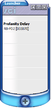
Open Sci The screen below will appear
If your unit is not already in the launcher list click the plus sign at the bottom of the launcher to discover devices.
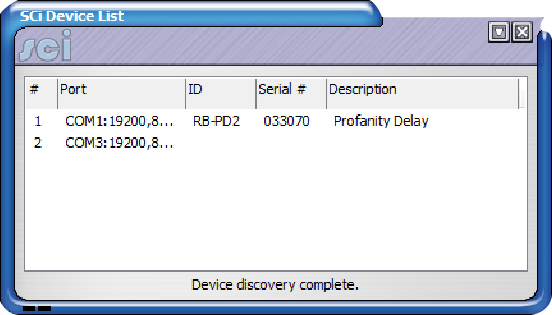
Click file and save to add your unit, then close the device discovery window and click on your device in the launcher window.
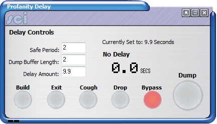
-
Click on the drop down box and select advanced upload firmware.
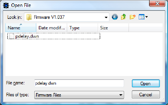
Browse to the directory that contains the file to upload
and click open.
The following screen will appear click the tick if you are using a USB to RS232 converter and the cross if not.
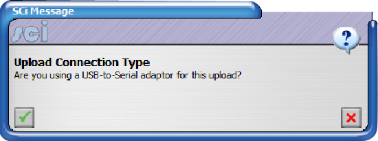
The upload should then begin.
Are there any recommended compact flash card for use with the RB-PD2?
We recommend using either Sandisk or Kingston compact flash cards, various cards from each of these manufacturers have been extensively tested with the PD2. Other types and manufacturers of card have not been tested and therefore we couldn't guarantee correct operation.
RB-SD1IP
Upgrading
When upgrading from an RB-SD1 to RB-SD1IP and using existing equipment connected to the remote connections, an adaptor cable will need to be made and plugged in between the remote equipment and the RB-SD1IP as per the following table:
| RB-SD1 Remote to RB-SD1IP Remote Conversion | ||
| RB-SD1 Remotes (Plug) | Function | RB-SD1 Unit (Socket) |
| 8 | Digital Ground | 1 |
| 7 | Restore Switch | 2 |
| 6 | Mode Indicator | 3 |
| 5 | Mode Switch | 4 |
| 4 | RLY 2 NC | 5 |
| 3 | RLY 2 NO | 6 |
| 2 | RLY 1 NC | 7 |
| 1 | RLY 1 NO | 8 |
| 15 | Remote Start | 9 |
| 14 | Source Select Switch | 10 |
| 13 | Source Select Ind | 11 |
| 12 | +5v | 12 |
| 11 | RLY 2 Common | 13 |
| 10 | Max Time (connect to gnd) | 14 |
| 9 | RLY 1 Common | 15 |
RB-SL2
How do I set up the RB-SL2 limiter?
The easiest way to set up the limiter is as follows, taking one channel at a time in mono mode : First turn the limit control to maximum (fully clockwise). Using an audio oscillator, inject a 1000Hz tone at 0dB (775mV into a 600 ohm load) at the input. Monitor the output with an audio analyser and adjust the gain control to give you the required output gain/attenuation. Next inject a tone at a higher level than you need to limit to (i.e. if you want to limit at 6dB higher than your output level, inject 7dB). Then turn the limit level anti-clockwise until the output reads the desired level and the LED on the front panel flashes (red/yellow for CH1 and green/yellow for CH2). In stereo mode CH1 controls the levels for both outputs.